6. Lens and aperture design
Ok, now I´m getting a bit more serious here. I´ve come up with a new design for the whole front peice of the camera and I suspect the back peice will look similar in style. The new idea is all based around cardboard and a number of slots. The frontmost for the lens, the middle one for the aperture and a very small back one for simple attachment and removal of the bellow. This is looking really good, solid and light. What I need to solve are how to attach this thing to a lego base and make it as sturdy as possible, but I have a pretty solid idea and it´s already on its way. This design have been done in detail in 3D studio and gives me a very good estimation on how the end product will look. Most of the peices will feature two layers of 1,5mm black cardboard, and when glued together thoroughly it will probably stand up to quite alot. I also added some curved lines here and there just to make it look way cooler than the lego bullshit I had previosly tried, and it´s completely light proof and will be as compact as it can be. With this design there will naturally be less lego parts used on the actual camera, but materialwise it will be even cheaper than lego anyway.
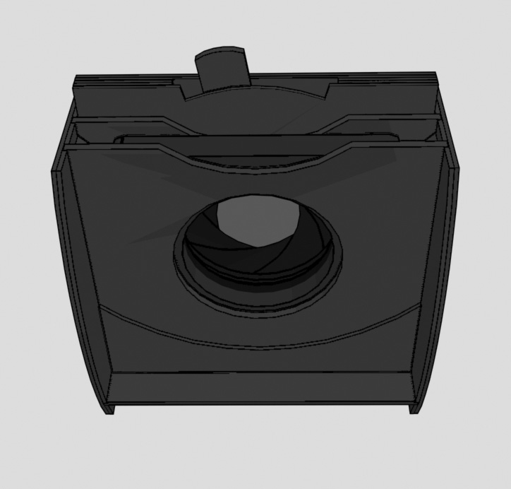
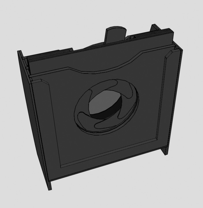
The best thing here though must be the compact aperture diaphragm I´ve made. I made some research on how these mechanisms work on real cameras and this is pretty much exactly the same. One ring revolves around another one which hold the blades. The outer ring pushes the blades which has a guide on the bottom that follows a slit in the ring, one for each blade. I have this all set up and animated in 3D studio so I´m pretty damn sure it will work. Now I just need to find out exactly which materials I need. The outer case will still be made from the same kind if cardboard as the rest of the front peice. But for the mechanichal parts and the aperture blades I might find something better than that. To start with I will probably cut some parts out of plastic styrene sheet which would create less friction when moving inside the case, then the only thing thats left are the pins that connects the blades to the case but i have some ideas I will try here as well. It wont be any fancy metal construction that´s for sure. I wonder if I can get hold of some sheets of carbon fibre or something similar. I can always make this part a few millimeters thicker if neccessary, it wont make any difference.
Calculating the F-stops I get is easy. By dividing the lens focal length with the diameter of the aperture opening you get the F number. In it´s most open state which is 40mm I get I get F2,5 when using the 100mm lens, and F7,5 with the 300mm lens. At it´s highest setting I intend to use on the scale, a 5mm opening I get F20 with the 100mm lens and F60 with the 300mm lens. Of course I could go down to one mm in aperture opening but at this end of the range the F stops will be harder to calculate and control due to the extremly small adjustments that is needed on the aperture controller (the lever that sticks up on the top of the construction. I will make a scale with numbers and attach on the front along the curved part below the lever.
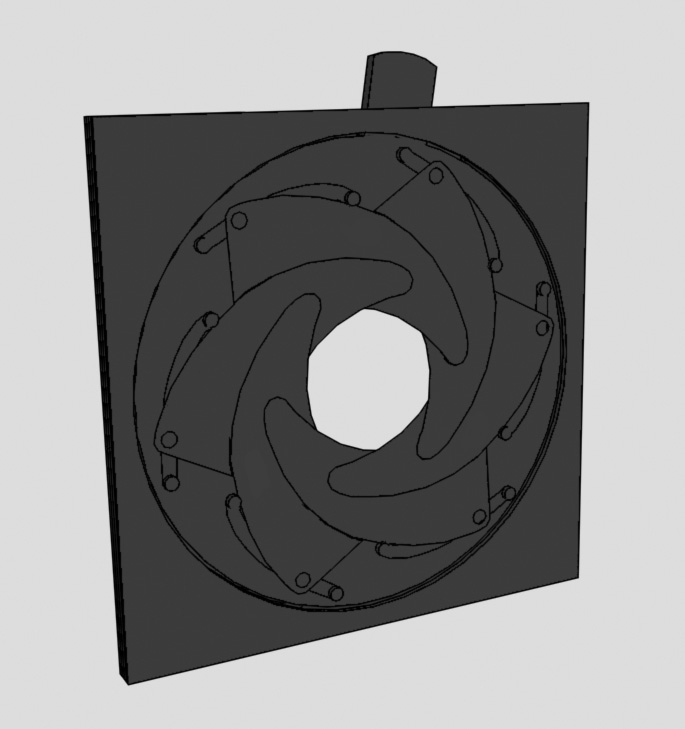
I will continue to design the back peice for the camera the same way I have done this. As that one is done I can start look at the bellow, then I´m pretty much done, Well almost, I just have to build the damn thing for real as well :) But this really looks promising.
Continue to chapter 7. Camera back and film holder design